Download Frequency Modulation Png Gantt Chart Excel Template
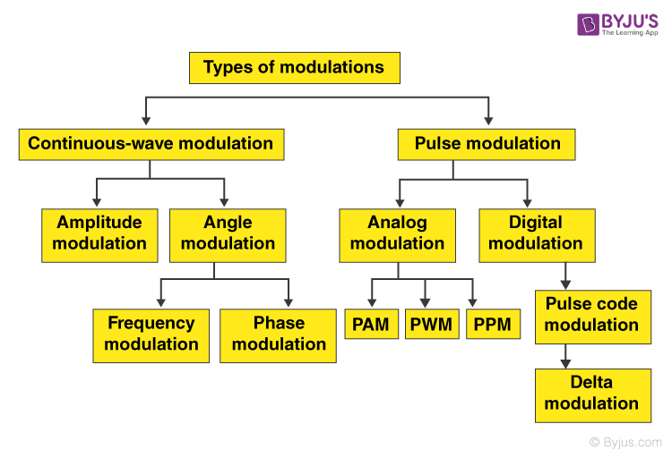
A block diagram showing the basic classification of modulation techniques is given below: Also, Read: Amplitude Modulation Frequency Modulation Types of Pulse Modulation Lets us look at some of the different types of pulse modulation. Pulse Amplitude Modulation (PAM) It is the simplest form of pulse modulation.

Simplified schematic diagram of the pulse width modulator block. Download Scientific Diagram
The figure below shows the block diagram of a PAM generator As we can see it consist of a low pass filter, a modulator along with a train generator and a pulse reshaping circuit. Here the modulating signal is given to the low pass filter in order to band limit the message signal.
27 High Level Block Diagram Wiring Diagram List
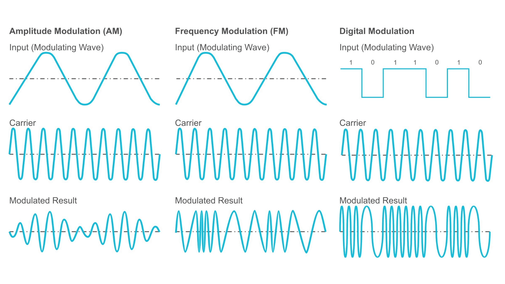
The process by which data/information is converted into electrical/digital signals for transferring that signal over a medium is called modulation. It increases strength for maximum reach of the signals. The process of extracting information/data from the transmitted signal is called demodulation.

Pulse Code Modulation(PCM) Block Diagram, Working Principle ETechnoG
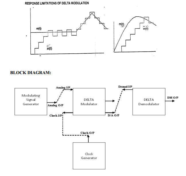
Block Diagram of Delta Modulator The sampling rate is comparatively very high in the delta modulation technique. The value of the step size after quantization is smaller. In the delta modulation process, the quantization design is easy and simple, and it gives the user the option to design the bit rate.
Principal Of Communication Notes (Amplitude Modulation Definition, Types, )
Adaptive Delta Modulation - Block Diagram and Applications. In communication systems, the modulation methods are used to transmit signals over long distances. In the modulation process, the properties of a high-frequency signal such as amplitude, phase, etc… are changed according to the low-frequency base-band signal.

Differential modulation block diagram for (a) QPSK, and (b) 16 QAM (τ... Download Scientific
Figure 1: Communication System Block Diagram Information Signal In order to send these electromagnetic waves across free space the frequency of the transmitted signal must be quite high compared to the frequency of the information signal. For example the information signal in a cell phone is a voice signal with a bandwidth on the order of 4kHz.
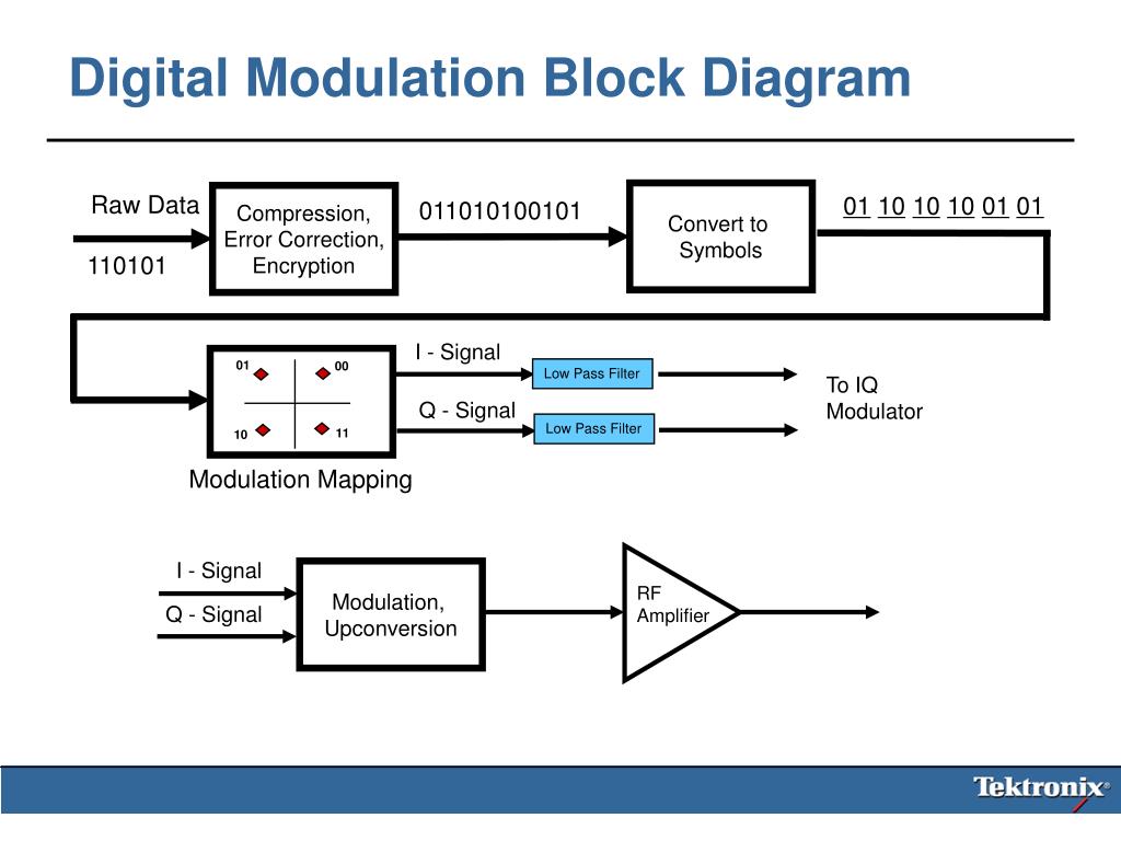
PPT WCA102 Fundamentals of Digital Modulation PowerPoint Presentation ID410205
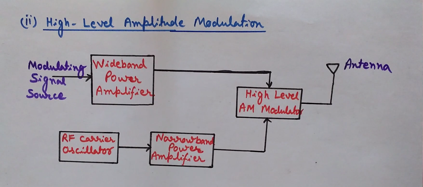
Block Diagram of Modulation Types Of Modulation Analog Modulation Amplitude Modulation Mathematical Representation Frequency Spectrum AM Transmitter Oscillator Power Amplifier Class A Power Amplifier Class B Power Amplifier Class C Power Amplifier Low-Level AM Transmitter High-Level AM Transmitter Advantages of AM Disadvantages of AM

Modulation Techniques Block Diagram Types of MODULATION YouTube
Figure 2.13.4: Quadrature modulator block diagram. In PSK modulation i(t) and q(t) have the same amplitude and indicate a phase ϕ of the modulated carrier so that i(t) = cos[ϕ(t)] and q(t) = sin[ϕ(t)]. The particular example shows two possible values of Ik and Qk and this indicates QPSK modulation. the modulated signal.
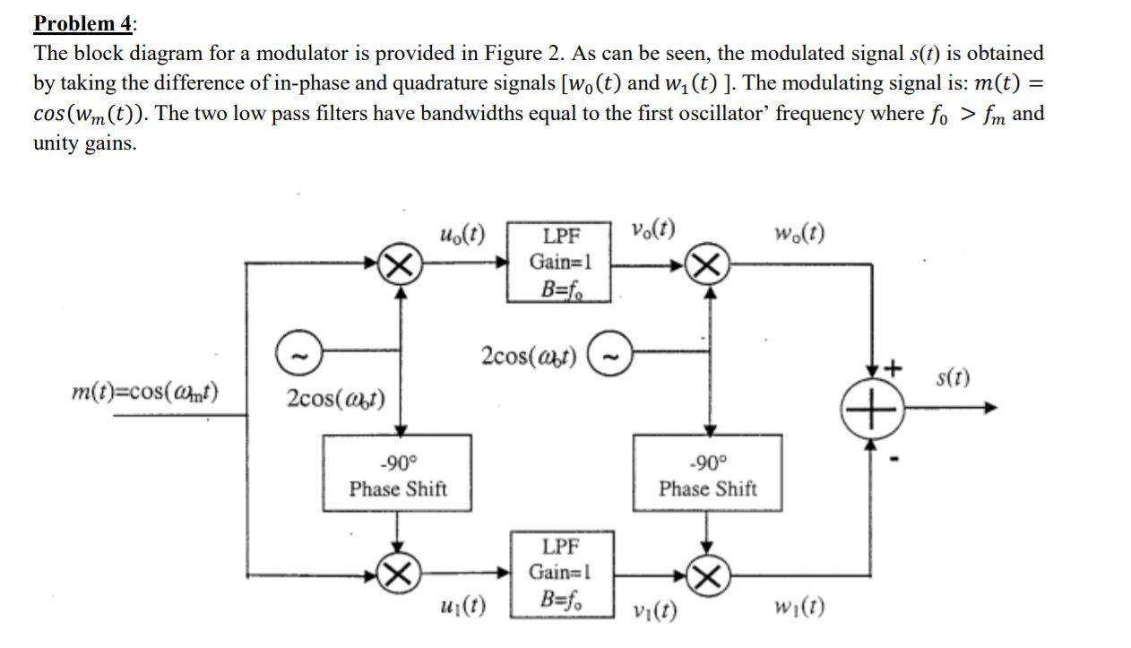
Solved Problem 4 The block diagram for a modulator is
Figure 2: A simple block diagram of delta modulation technique Applications of the Delta Modulation technique Generally, the Delta Modulation method is used where the signal quality has low importance, as it is the simplest version of DPCM, and it does not have a significant accuracy, especially when signal changes are too high or near zero.

Frequency modulation block diagram Download Scientific Diagram
Fig.3 GMSK Modulation Block Diagram As shown in the GMSK modulator Gaussian filter is applied to NRZ signal after it is passed through integrator block. This gives Φ. By applying COS and SIN function to this Φ gives out I and Q components which bits with cos and sin function respectively using mixing function. Both the chains are summed up.

10 QPSK Modulator Block diagram Download Scientific Diagram
Delta-sigma (ΔΣ; or sigma-delta, ΣΔ) modulation is an oversampling method for encoding signals into low bit depth digital signals at a very high sample-frequency as part of the process of delta-sigma analog-to-digital converters (ADCs) and digital-to-analog converters (DACs). Delta-sigma modulation achieves high quality by utilizing a negative feedback loop during quantization to the lower.
Phaselocked Loop Modulation Block Diagram Signal, PNG, 1049x1024px, Phaselocked Loop, Area
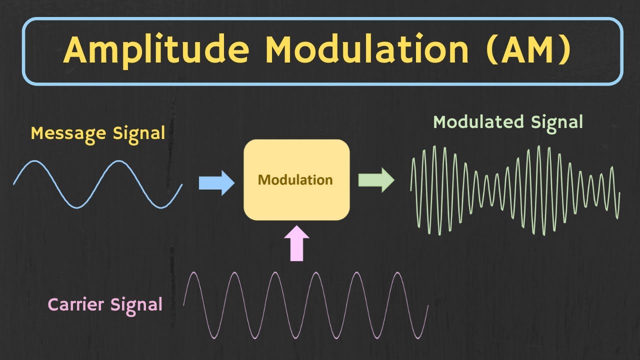
Amplitude Modulation Block Diagram Here the modulating signals might be an audio or video signal. These are also called as baseband signals as these are modulated with the carrier signals. Carriers are extremely high-frequency radio signals, In general, carrier signals are received from the RF oscillators.
Delta Modulation
Block diagram of Pulse Code Modulation The figure below shows the block diagram representing a PCM system It is basically composed of a transmitter, a transmission path and a receiver. The transmitter performs the sampling, quantizing and encoding of the signal.
Pulse Modulation Definition, Types, Block Diagrams, Pulse Modulation Width
The block diagram of adaptive delta modulation is shown below which includes an ADM transmitter & receiver. The transmitter has a summer, a quantizer, a delay circuit, and a logic circuit. Here, the step size is kept fixed between some predefined maximum and minimum values. Adaptive Delta Modulation Transmitter.
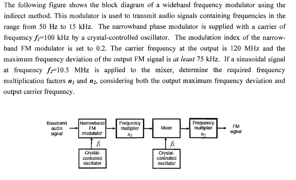
The following figure shows the block diagram of a
Amplitude Modulation Block Diagram. Generation of Amplitude Modulation : There are two types of devices in which it may be necessary to the Generation of Amplitude Modulation. The first of these, the AM transmitter, generates such high powers that its prime requirement is efficiency, so quite complex means of AM generation may be used.

PPM Pulse Position Modulation Block diagram, Waveforms, Advantages, Disadvantages
QAM can be defined as it is s a modulation technique that is used to combine two amplitude modulated waves into a single channel to increase the channel bandwidth. Quadrature Amplitude Modulation Block Diagram The below diagrams show the transmitter and receiver block diagram of the QAM scheme. QAM Modulator qam-modulator QAM Demodulator